
software resources for science and technology education


Mr Bit Sensor Starter Kit
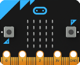
Connecting sensors and controlling devices with your micro:bit is not as hard as you might think:
Try out the Mr Bit Starter Kit!
This DIY kit has been designed with younger pupils in mind. It consists of a buzzer, 3 LED set, light sensor and temperature sensor. The components are inexpensive and readily available, and the only tools needed are a small screwdriver, hacksaw, pliers and wire stripper. When you have built your kit, you are ready to start work with Mr Bit Experiments.
Connecting leads
Leads with 4mm plugs are recommended, since they fit snugly in the pin sockets and provide more secure connection than do crocodile clips. The stackable variety of plug is desirable, to allow multiple connections to the pins, particularly important for the 3V and GND pins. Leads purchased with moulded plugs at each end may be cut in half to provide two connectors.
The following colour convention is suggested to facilitate correct connections and minimise errors:
- RED to 3V
- BLACK to GND (0V)
- YELLOW to input pin
- GREEN to output pin.


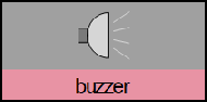
This output device is a piezo electric crystal incorporating a circuit for producing a single frequency sound when a voltage is applied. It is necessary to observe the polarity with the black lead connected to GND.
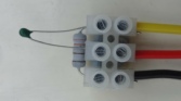
DIY tip: Mount the buzzer on a small block of wood and connect the leads with a terminal
block as shown. This makes a more robust device for classroom use and helps to protect
the rather fragile wires emerging from the buzzer. It is important to purchase the
device with a built-


This output device with red, yellow and green LEDs, is an integrated unit containing the required current limiting resistors. It simplifies the number of connections when two or three LEDs are used. For all uses, the black lead must be connected to GND.
DIY tip: The connecting leads may be secured by threading the bare wires through each socket hole and twisting. Cover the sockets on both sides with insulation tape to secure the connections.
See download notes for recommended components.


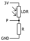
The light level sensor uses a light dependent resistor (LDR) in series with a resistor. When the full 3 volts is connected across the combination, the voltage across the resistor varies as the incident light level changes, and this may be used as an analogue input
signal. There are three connecting leads: red to 3V, black to GND and yellow to P0, P1 or P2. The micro:bit shows the light level as a percentage of a maximum.
LDR: NSL511. R: 10k.
DIY tip: The resistor most conveniently fits into the end terminals of the 3-
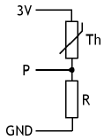
The temperature sensitive component is a thermistor, but it is always used in series with a resistor to create a potential divider circuit. The voltage across the resistor varies as the temperature changes, and this is used as an analogue input signal.
There are three connecting leads: red to 3V, black to GND and the yellow to P0, P1 or P2.
Th: Thermistor 10k NTC. R: Resistor 3K3 1%.
DIY tip: Using the recommended components, the micro:bit shows a Celsius value between 15 and 35ºC. Outside these limits, error exceeds 2ºC.
N.B. This simple sensor construction is not suitable for immersion in water. However, in order to achieve cooling, the thermistor bead might be touched against a wet sponge or tissue paper.
Pins P0 P1 P2
© 2024 Insight Resources